
Appearance
Example
Follow these procedures to create a Door Job from the blueprint described in the introduction.
Create a Door Job
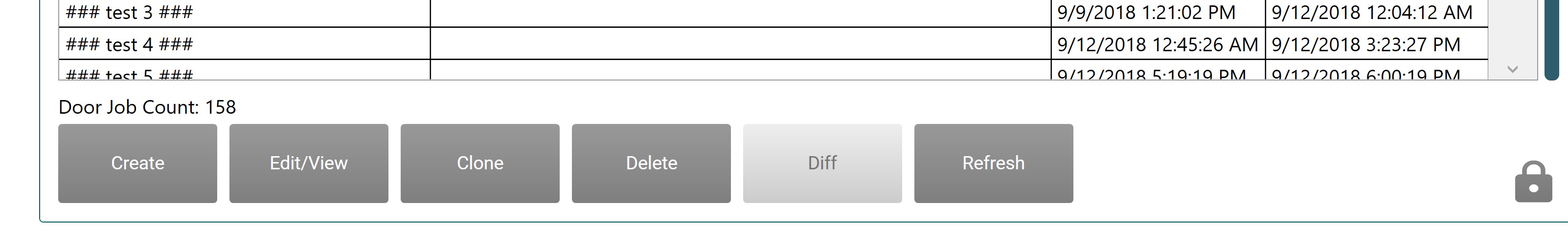
Click the Door Job Library tab, then click the Create button.
Name The Door Job
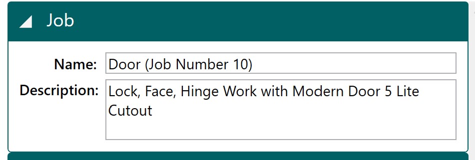
Fill the Name and Description fields.
INFO
An astrix (*) next to title indicates the file has unsaved changes.
Add Door Data
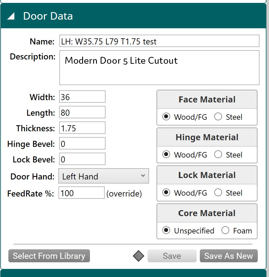
- Enter the information in the Name and Description fields.
- Enter the door parameter data listed in the table below into their corresponding fields.
- The door is wooden. Select the Wood/FG Material check boxes. (Face, Hinge, Lock, and Core)
Enter the following into the associated parameters.
| Width | Length | Thickness | Hand | Lock Bevel (deg) | Hinge Bevel (deg) |
|---|---|---|---|---|---|
| 36 | 80 | 1.75 | Left Hand | 0 | 0 |
INFO
The normal setting for FeedRate is 100%
Create a Lock Feature Group
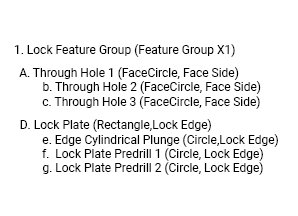
The Lock Feature Group portion of the Door Job can be organized into two Features with associated Feature Children.
| Lock Feature Group | Illustration |
|---|---|
 | 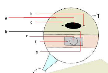 |
The Lock
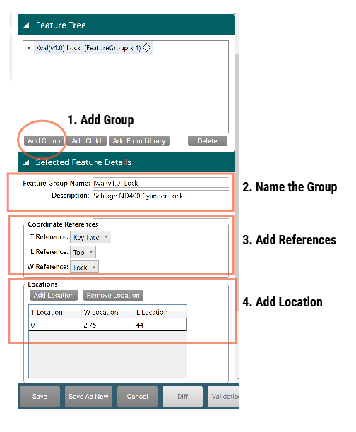
- Select the Add Group Button
- At the Selected Feature Details Panel, input text into Feature Group Name and Description.
- At the Coordinated References area set the cut references. From the drop-down menu use the settings outlined in the table below.
| Parameter | Selection | Notes |
|---|---|---|
| T Reference | Key Face (The side the key is used to open the door) | Thickness |
| L Reference | Top (Reference from the top of the door to the middle of the lock circle cut) | Length |
| W Reference | Select Lock (The lock side of the door not the hinge side) | Width |
- At the Locations section, enter the locations of the Lock Cut Features outlined in the table below.
| Parameter | Enter | Notes |
|---|---|---|
| W Location | 2.75 inches | Location on the width of the door |
| L Location | 44 inches | Location on the length of the door |
The Lock Plate
First, create an edge rectangle located on the lock edge of the door. Use the specifications in the table below to create your shape. Keep an eye on the Job Preview Screen to observe as the shape is built.
| Call Out | Feature Name (Edge of Door) | Qty | Depth | Bevel | Length | Width | Radius |
|---|---|---|---|---|---|---|---|
| D | Lock Plate (Rectangle,Lock Edge) | 1 | 0.156 | 0 | 2.25 | 1.25 | 0 |
The final display should look like the image below.
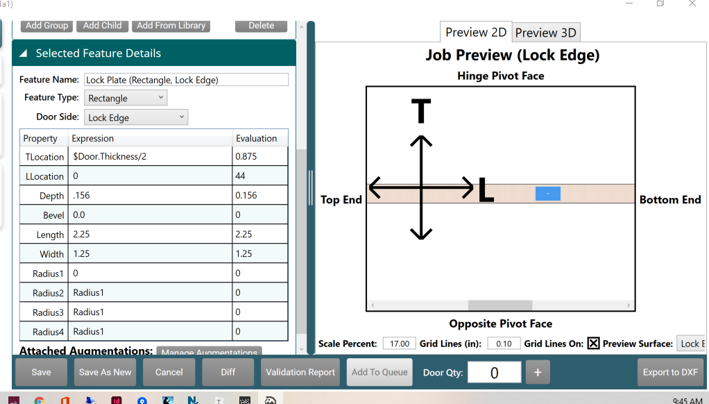
- Select Add Child to the Feature Group.
- At the Selected Feature Details panel, input descriptive text into Feature Name .
- From the drop-down menu of Feature Type select Rectangle. (This is the Lock Plate)
- From the drop-down menu of Door Side select Lock Edge. (Location of the rectangle shape)
- In the Properties Table, enter the data from the table above.
| Property | Data | Notes |
|---|---|---|
| TLocation | Enter" $Door.Thickness/2" | Location of cut on the edge of the door. Expression puts the cut in the middle of the edge of the door. |
| LLocation | Keep at 0 | Location referenced from the top of the door. The Lock Edge location was set at the Feature Group Level |
| Depth | Enter .156 | The depth of the Lock Plate |
| Bevel | No Bevel | Either 0 or 3 degrees |
| Length | Enter 2.25 | Length of the Lock Plate |
| **Width ** | Enter 1.25 | The width of the Lock Plate |
| Radius | Enter 0 | This cut has square edges |
Add Children to the Lock Plate Feature
Add children associated with the lock edge cut. (Plunge and Edge Plate Predrills)
| Call Out | Feature Name (Edge of Door) | Qty | Bevel | Diameter |
|---|---|---|---|---|
| e | Edge Cylindrical Plunge (Circle,Lock Edge) | 1 | 0 | 1 |
| f | Lock Plate Predrill 1 (Circle, Lock Edge) | 1 | 0 | 0.16 |
| g | Lock Plate Predrill 2 (Circle, Lock Edge) | 1 | 0 | 0.16 |
Create Edge Cylindrical Plunge
The Plunge Cut is the main lock hole on the edge of the door.
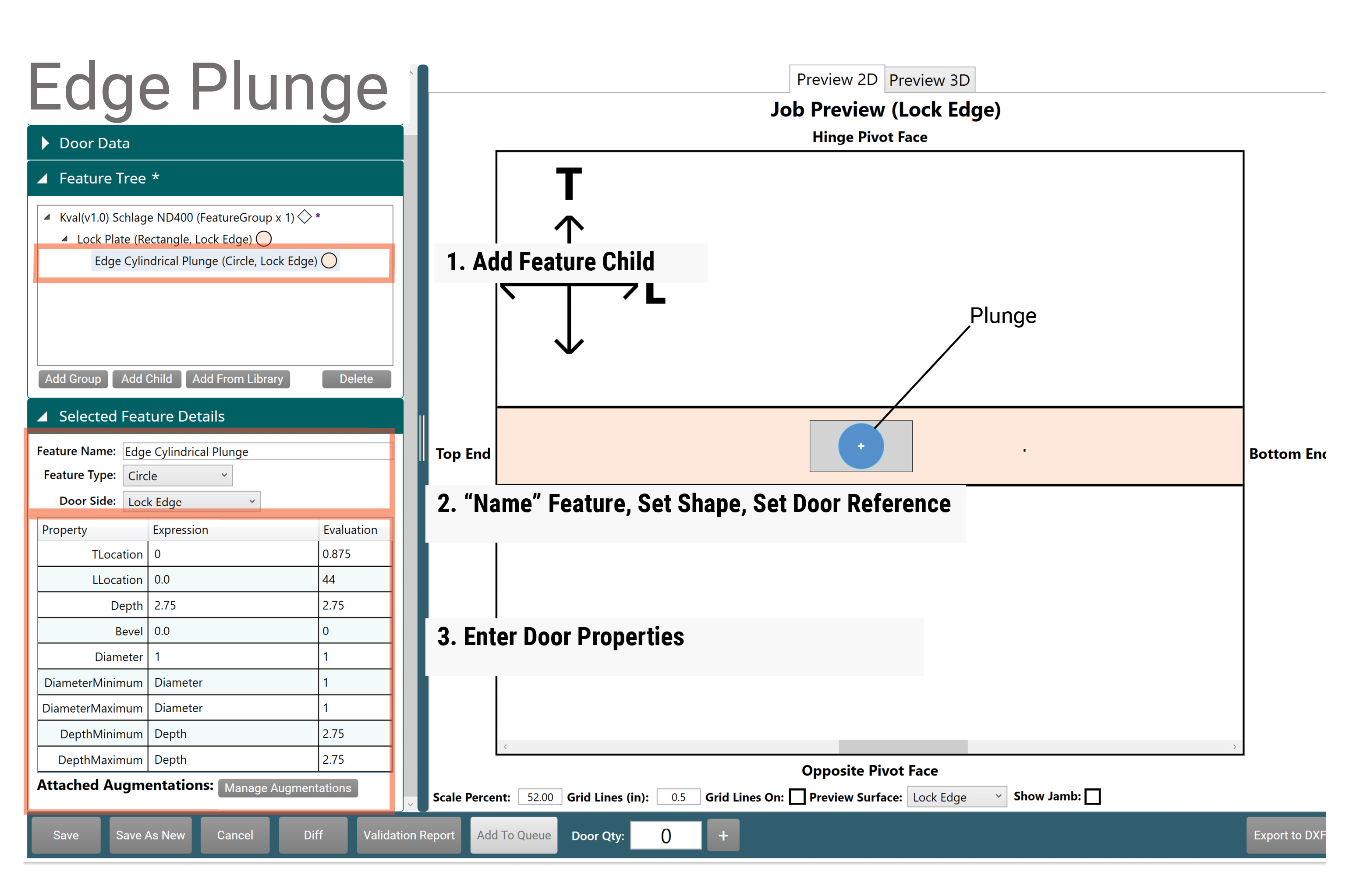
- Select to highlight the Lock Plate then select Add Child.
- At the Selected Feature Details panel, input descriptive text into Feature Name.
- From the drop-down menu of Feature Type select Circle. (This is the plunge cut)
- From the drop-down menu of Door Side select Lock Edge. (Location of the circle shape)
- In the Properties Table, enter the data from the table above.
| Property | Data | Notes |
|---|---|---|
| TLocation | 0 | (Location=middle of the edges of the door) The location was set in the Lock Plate feature level. (0 + 0.875 = 0.875) |
| LLocation | 0 | (Location referenced from the top of the door) The location was set in the Feature Group level. (0 + 44 = 44) |
| Depth | 2.75 | The depth of the Lock Plate |
| Bevel | No Bevel | Either 0 or 3 degrees |
| Diameter | 1 | |
| DiameterMinimum | 1 | |
| DiameterMaximum | 1 | |
| DepthMinimum | 2.75 | |
| DepthMaximum | 2.75 |
Lock Plate Predrill 1 and 2
Add the predrill holes to the lock plate. These are the locations to secure the door lock face plate to the edge of the door.
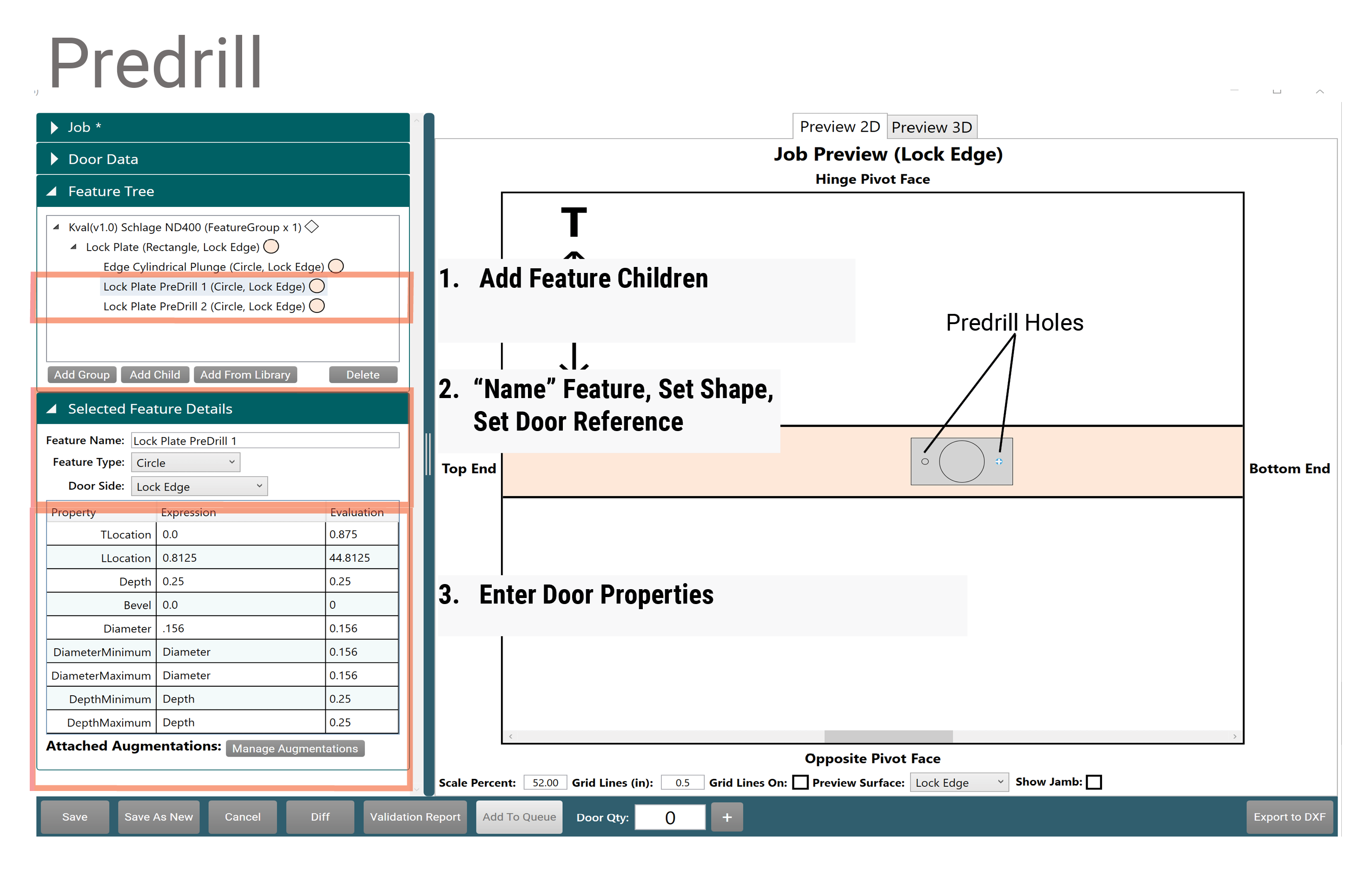
Lock Plate Predrill 1
- Select to highlight the Lock Plate then select Add Child.
- At the Selected Feature Details panel, input descriptive text into Feature Name.
- From the drop-down menu of Feature Type select Circle. (This is the plunge cut)
- From the drop-down menu of Door Side select Lock Edge. (Location of the circle shape)
- In the Properties Table, Enter the specifications from the table above
| Property | Data | Note |
|---|---|---|
| TLocation: | 0 | Location=middle of the edges of the door. The location was set in the Lock Plate feature level. (0 + 0.875 = 0.875) |
| LLocation | 0.8125 | Location referenced from the middle of the Plunge. This location is furthest for the Top Reference (44.0 + 0.815= 44.815) |
| Depth | .25 | |
| Bevel | None | |
| Diameter | .156 |
For the remaining Diameter and Depth expression enter the original values.
Lock Plate Predrill 2 (Cut and Paste)
TIP
Create a shape using the cut-and-paste option.
- Right click to highlight Lock Plate Pre Drill 1.
- From the Popup window, select Copy Selected.
- Right click anywhere in the Feature Tree area and select Paste Circle.
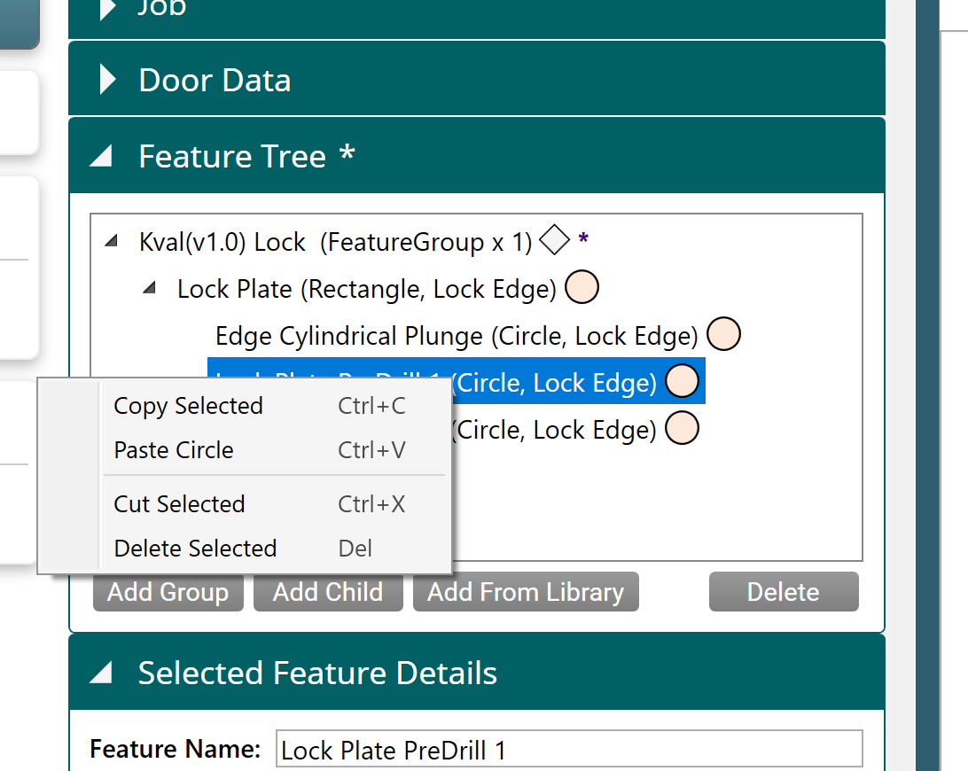
- At Feature Details, change Feature Name to Lock Plate Pre Drill 2.
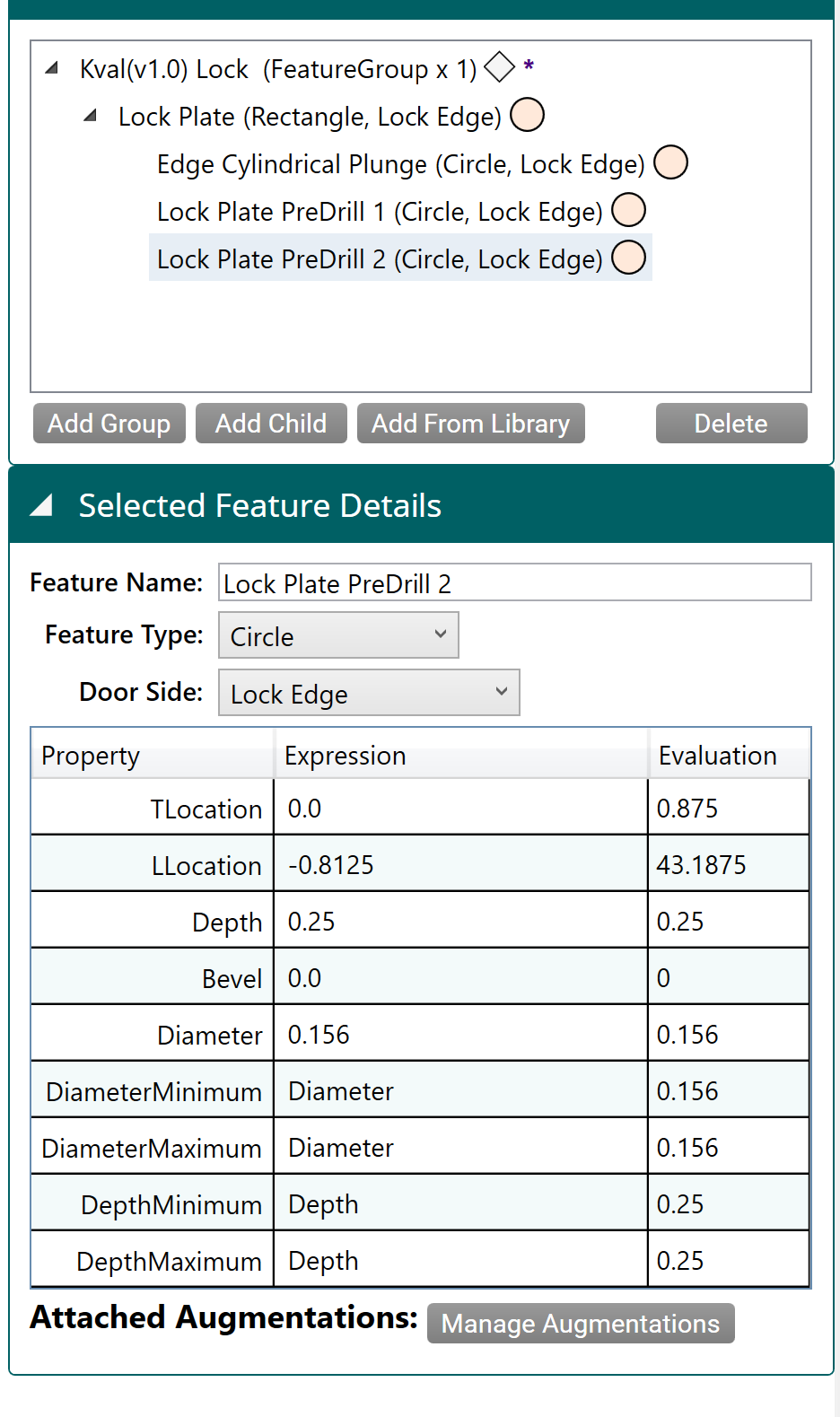
- At Feature Details, change LLocation to the following:
| Property | Data | Notes |
|---|---|---|
| LLocation | Enter -0.8125 | Location = (44.0 - 0.8125 = 43.1875). |
Lock Face Cuts
Under the Lock Plate Feature Group, build a new Feature with Children.
Table of Specifications:
| Call Out | Features (Face of Door) | Qty | Depth | Dia. |
|---|---|---|---|---|
| A (Feature) | Face Plunge (FaceCircle,Lock Edge) | 1 | 1.75 | 2.125 |
| b (Child) | Through Hole 2 (FaceCircle,Lock Edge) | 1 | 1.75 | 0.25 |
| c (Child) | Through Hole 3 (FaceCircle,Lock Edge) | 1 | 1.75 | 0.25 |
Create the Face Plunge
The final face plunge display should look like the image below.
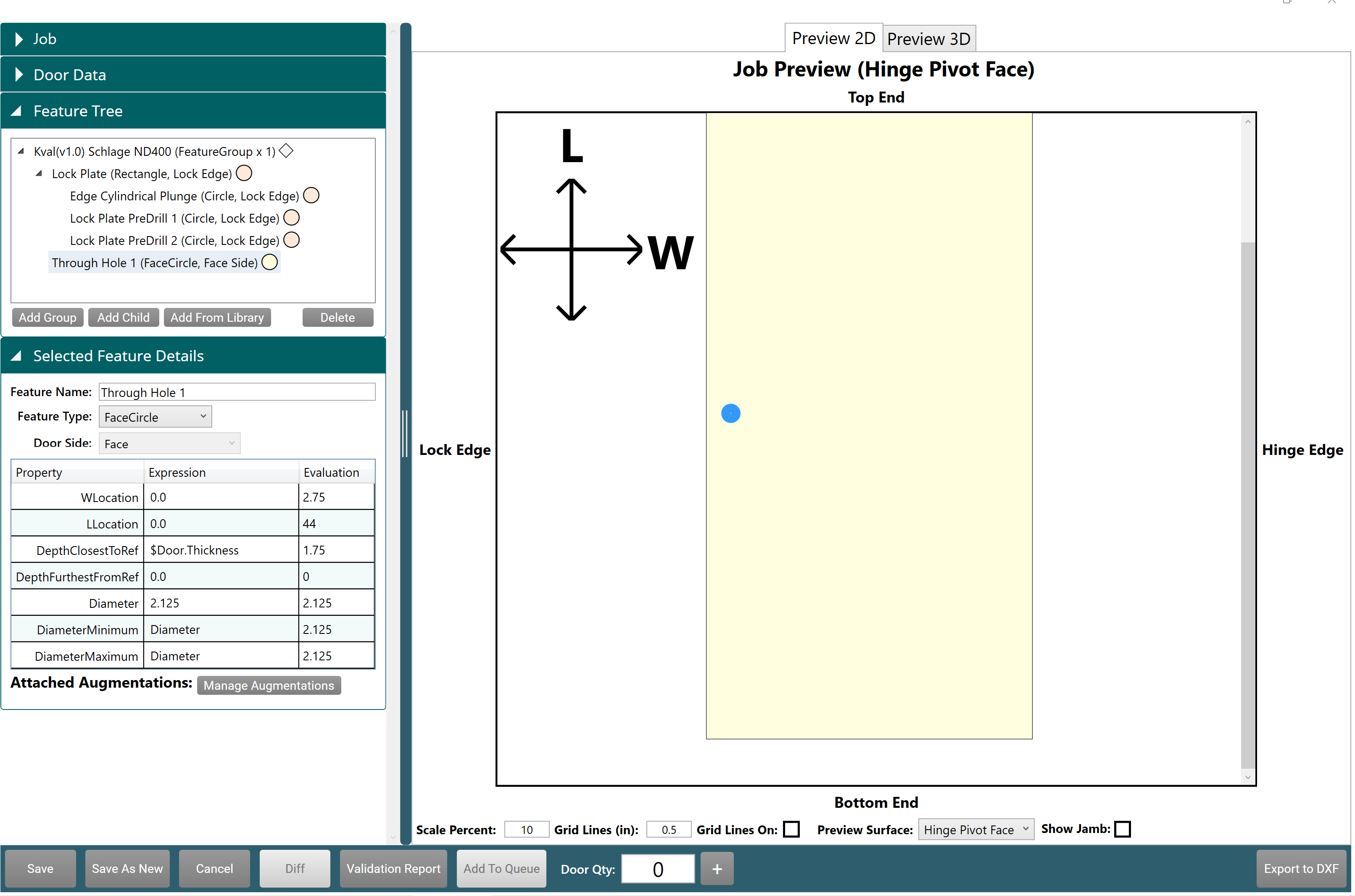
- Select to highlight the Lock Plate then select Add Child.
- At the Selected Feature Details panel, input descriptive text into Feature Name field.
- From the drop-down menu of the Feature Type, select FaceCircle. (This is the Lock Face cut shape)
- From the drop-down menu of Door Side, select Face. (Location of the circle shape)
- In the Properties Table, enter the specifications from the table above.
| Property | Data | Notes |
|---|---|---|
| WLocation | 0 | Location was set to 2.75 at the Lock Plate Level |
| LLocation | 0 | Location referenced from the top of the door |
| DepthClosestToRef | 1.75 | Depth of the face lock hole |
| DepthFurthestToRef | 0 | |
| Diameter | 2.125 | Size of the face lock hole |
| DiameterMinimum | Diameter | No adjustment to Diameter |
| DiameterMaximum | Diameter | No adjustment to Diameter |
Create the Face Through Holes
Create the screw holes for the face lock.
Build a Hinge Feature Group
Create the locations of the hinges by way of a Feature Group.
- Hinge 1: at 6.75 inches
- Hinge 2: at 36.0 inches
- Hinge 3: at 62.25 inches
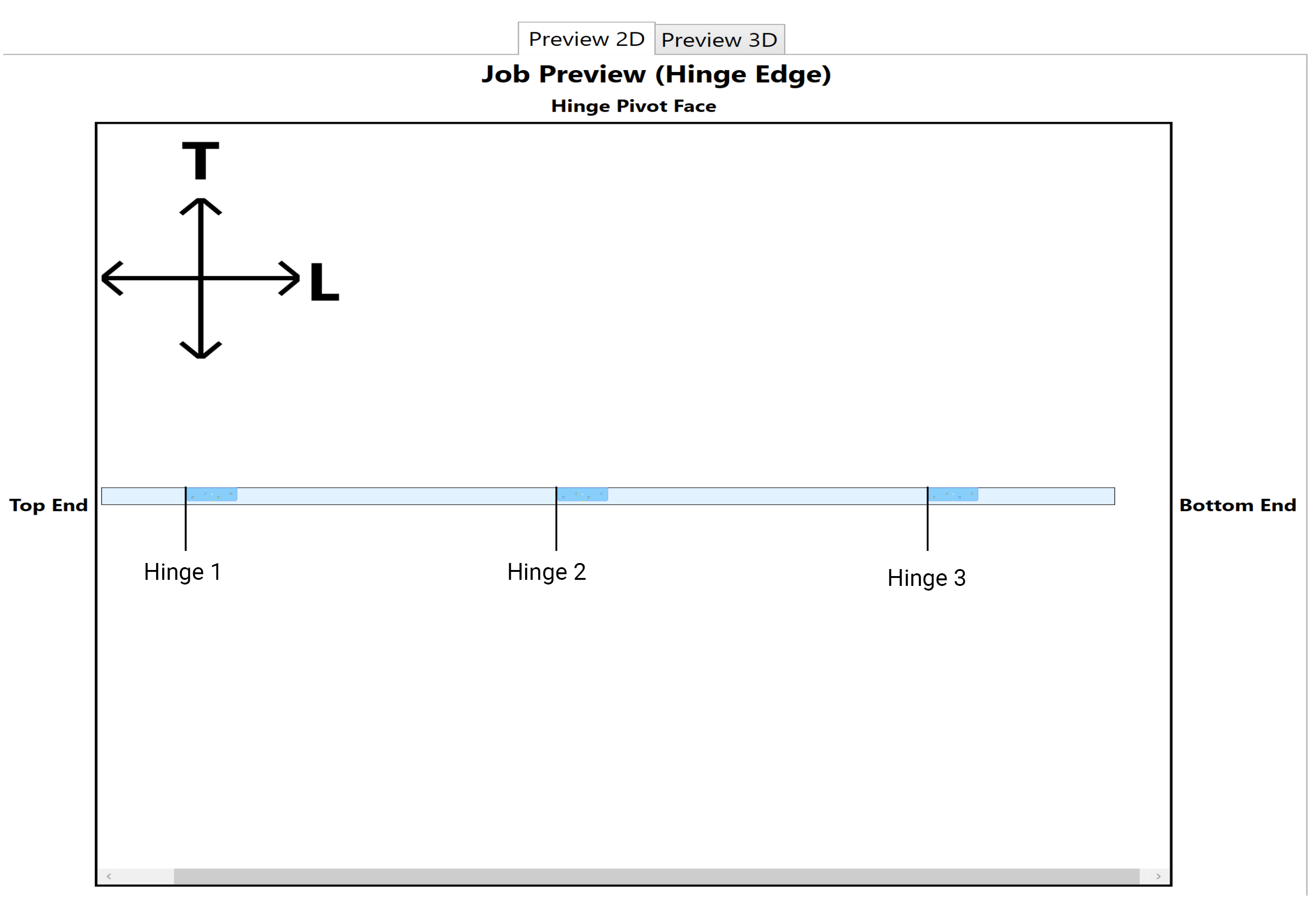
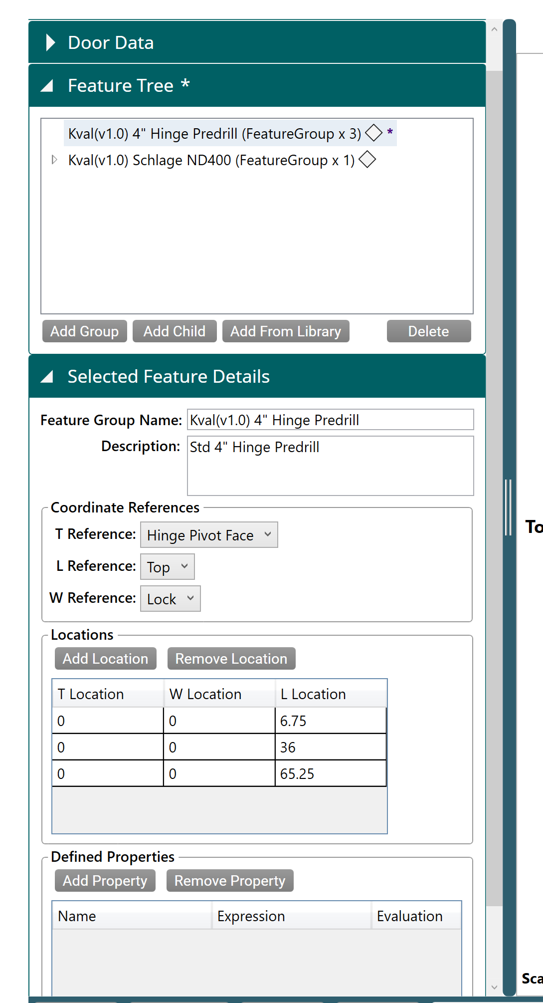
Create Hinge Feature Group
Create a Hinge Feature Group.
- Select the Add Group Button
- At the Selected Feature Details Panel, input information into Feature Group Name and Description.
- At the Coordinated References, set the cut references. From the drop-down menus , choose the following:
| Property | Data | Notes |
|---|---|---|
| T Reference | Select Hinge Pivot Face | (Thickness) The side where the hinge knuckle is located the door. |
| L Reference | Select Top | (Length) Reference from the top of the door to the middle of the hinge. |
| W Reference | Select Lock | (Width) The reference is the Lock side of the door. |
At the Locations area, set the locations of all 3 hinges. Leave the T Location and W Location s at zero.
| Location | Data | Notes |
|---|---|---|
| L Location | 6.75 | Location of first Hinge from the top of the door |
| L Location | 36.0 | Location of second Hinge from the top of the door |
| L Location | 65.25 | Location of third Hinge from the top of the door |
Create Hinge Feature
Enter the hinge cut features. The cut will be repeated 3 times located at the locations set in the Hinge Feature Group.
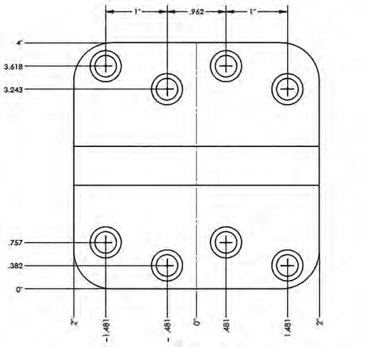
Table of Specifications:
| Name | QTY | Depth | Bevel | Length | Backset | Radius |
|---|---|---|---|---|---|---|
| Kval(v1.0) 4" Hinge Predrill | 1 | 0.125 | 0 | 4 | 0.375 | 0.25 |
The final hinge shape should look like the image below.
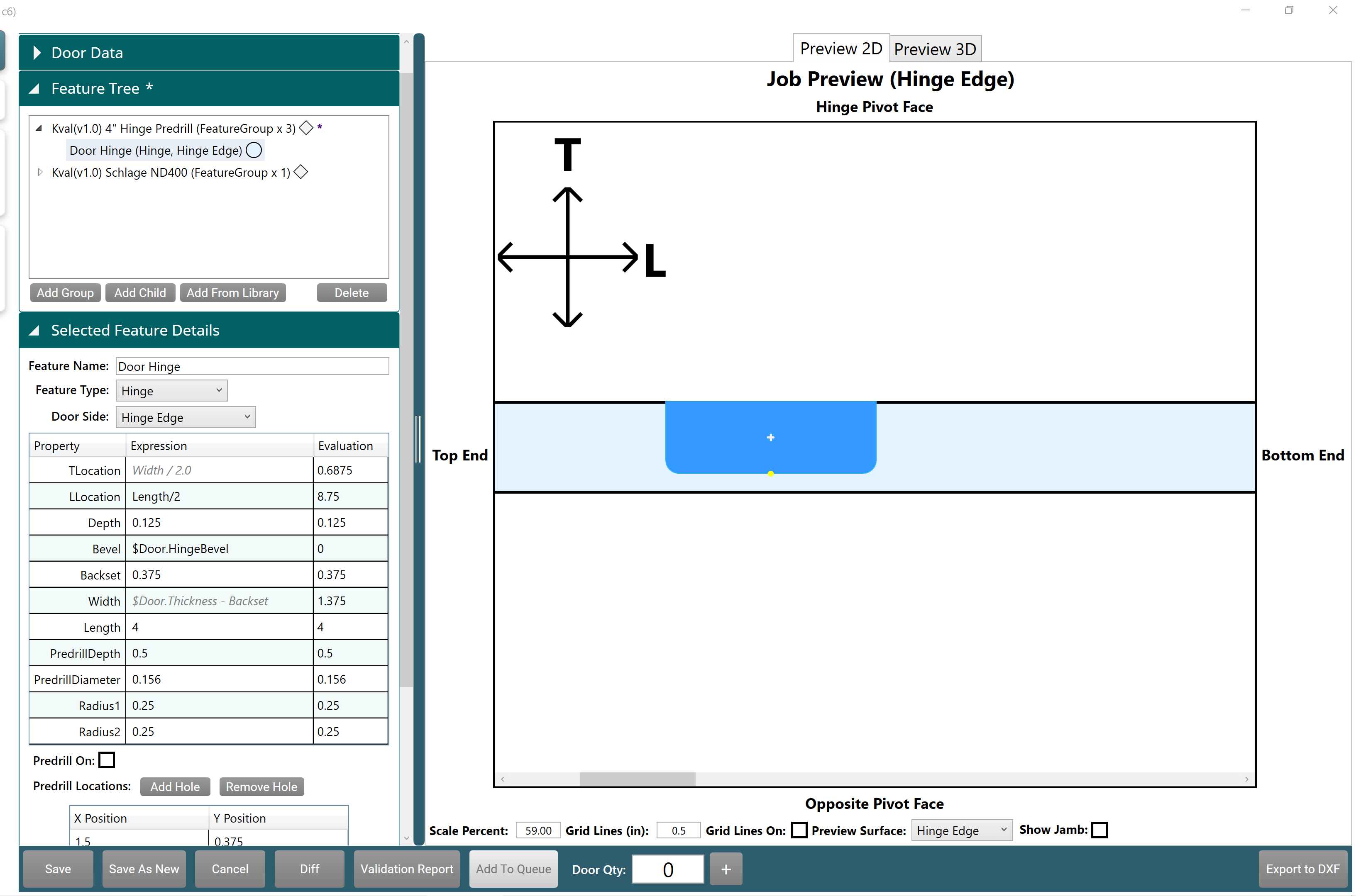
- Select to highlight the Hinge Predrill Feature Group and then select Add Child.
- At the Selected Feature Details panel, input descriptive text into Feature Name.
- From the drop-down menu of Feature Type, select Hinge. (This is the Hinge cut)
- From the drop-down menu of Door Side, select Hinge Edge. (Location of the Hinge cut)
- In the Properties Table, enter the specifications from the table above.
| Property | Data | Notes |
|---|---|---|
| TLocation | N/A | Preset by Feature Type (Hinge) |
| LLocation | Enter Length/2 | Sets the middle of the first Hinge Cut [(4/2) + 6.75 = 8.75] |
| Depth | Enter 0.125 | The depth of the Hinges |
| Bevel | 0 degree or $Door.HingeBevel | No Bevel |
| Backset | Enter 0.375 | Space between the edge of the door and the cut |
| Width | Enter 1.25 | The width of the Hinge |
| Length | Enter 4 | Length of the Hinge |
| PredrillDiameter: | Enter 0.156 | Set and monitored by Tool Config |
| Predrill Depth | Enter 0.5 | Depth of predrill holes |
| Radius 1 and 2 | Enter 0.25 | Rounds the corners of the hinges |
Add the Predrill Holes to the Hinge Cut
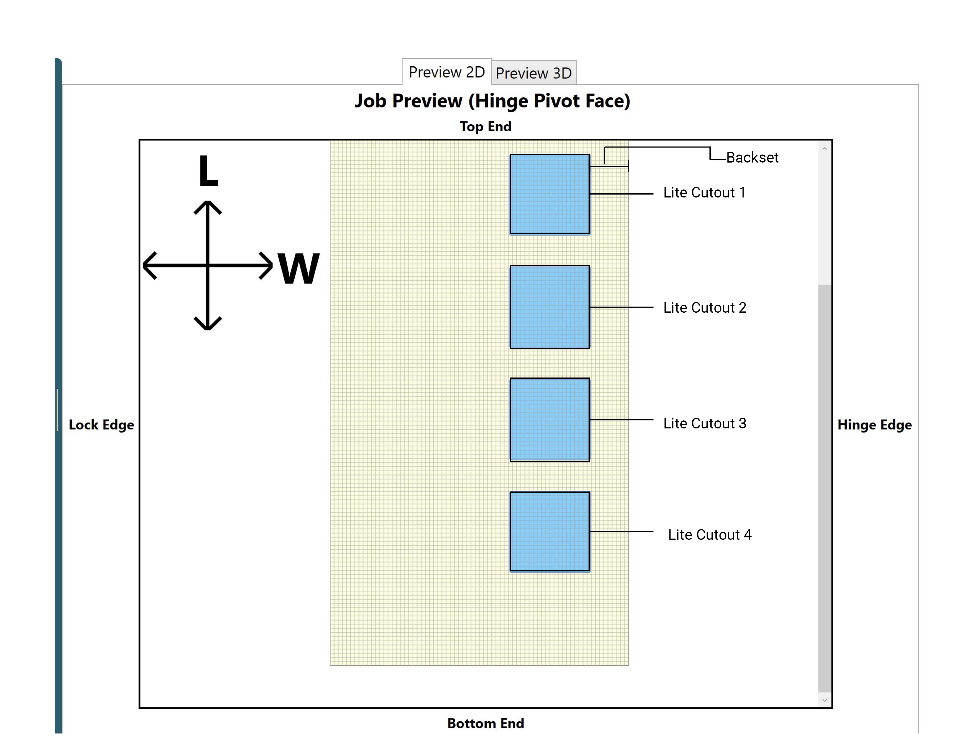
Build a Door Lite Feature Group
Create the locations of the Lite Cutouts by way of a Feature Group and Features.
- Backset: 9.47 inches ( Referenced from the Hinge Side)
- Lite Cutout 1: 23.16 inches
- Lite Cutout 2: 36.72 inches
- Lite Cutout 3: 50.28 inches
- Lite Cutout 4: 63.84 inches
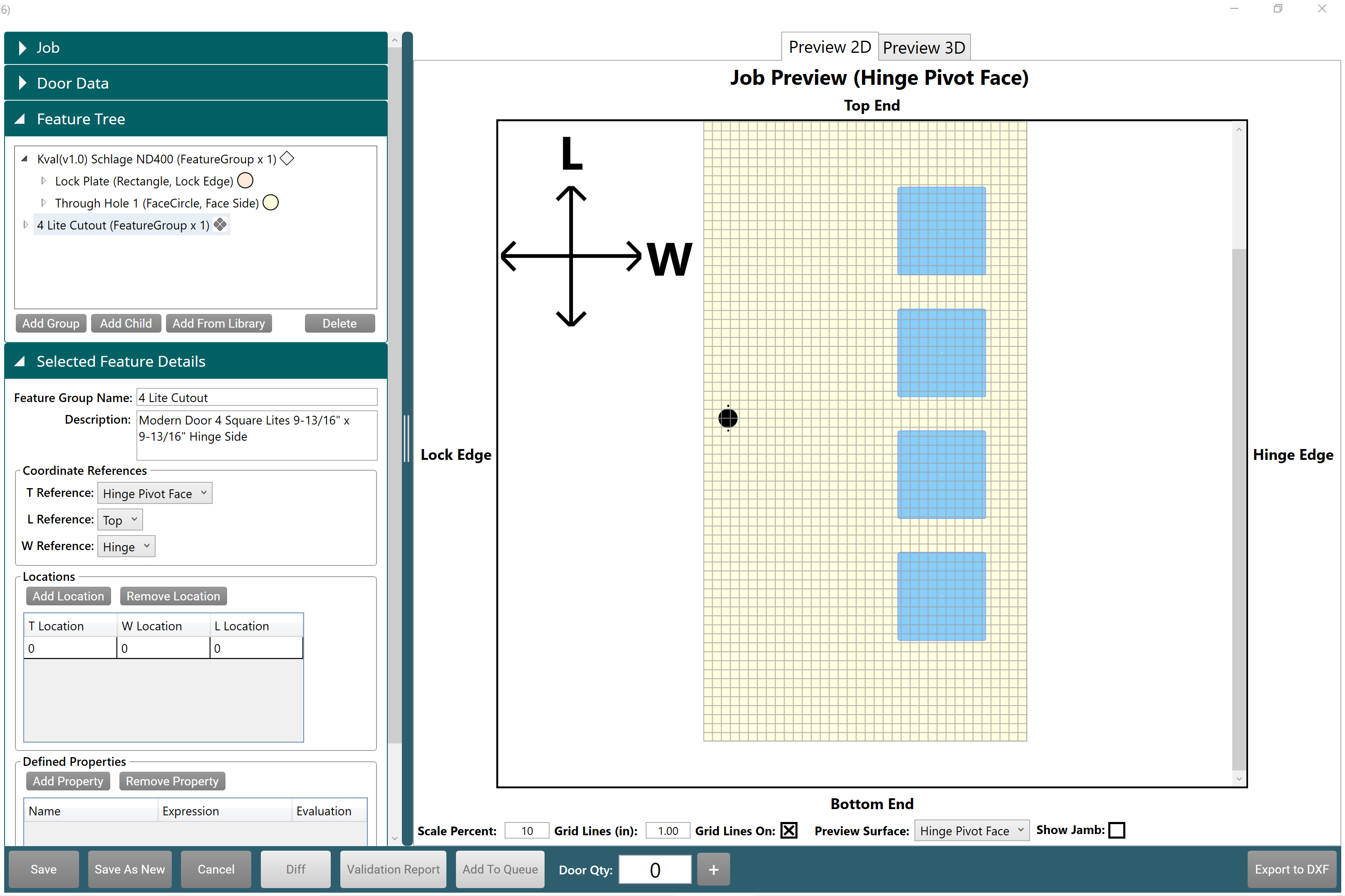
Create Lite Cutout Feature Group
- Select the Add Group Button
- At the Selected Feature Details Panel, input information into Feature Group Name and Description fields.
- At the Coordinated References, set the cut references. From the drop-down menus , choose the following:
| Property | Data | Notes |
|---|---|---|
| T Reference | Select Hinge Pivot Face | (Thickness) The side where the hinge knuckle is located the door. |
| L Reference | Select Top | (Length) Reference from the top of the door to the middle of the hinge. |
| W Reference | Select Hinge | (Width) The reference is the Hinge side of the door. |
- Leave Locations blank, the locations will be set in the Features of this group
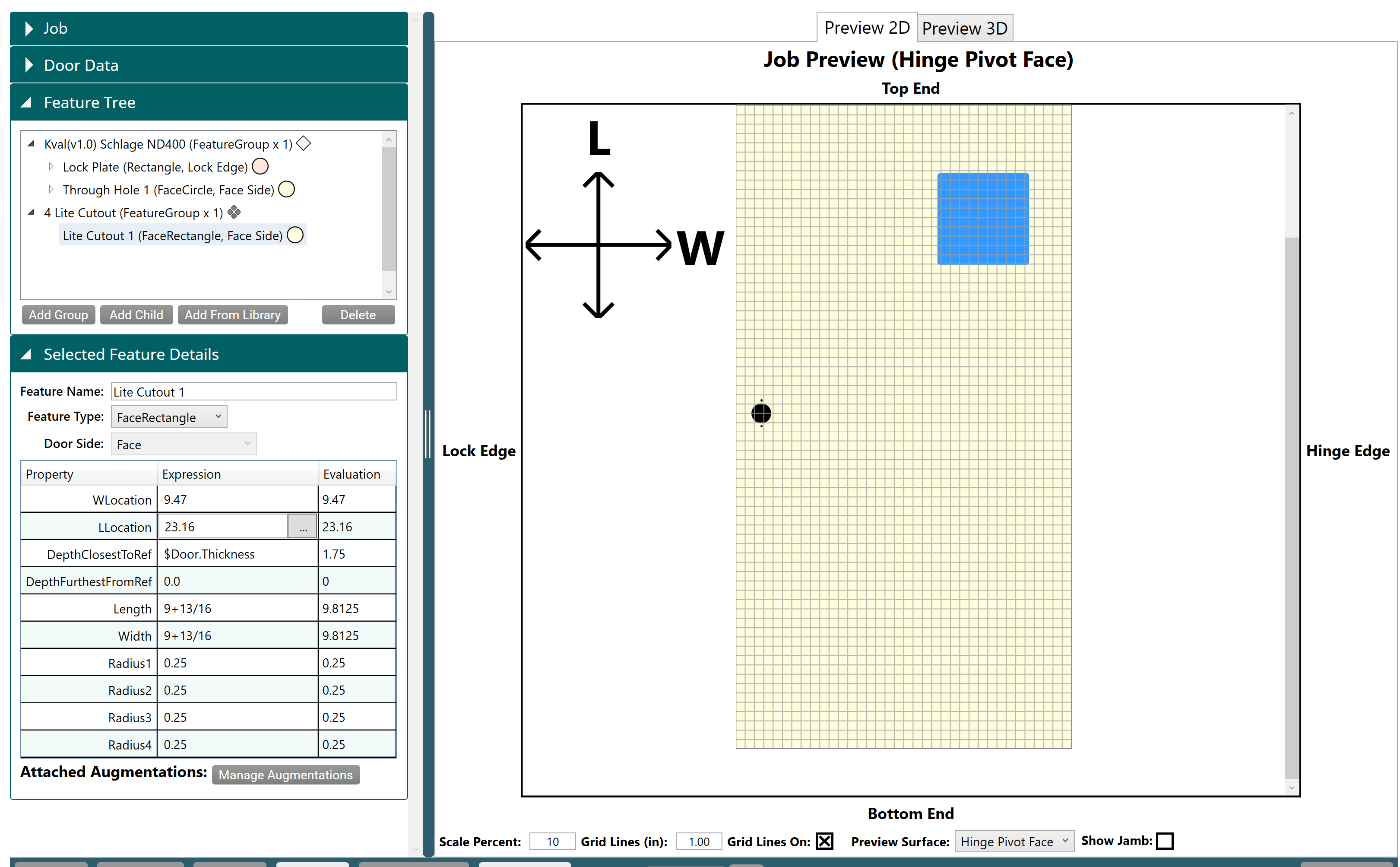
Add Lite Cutout 1 Features
| Feature Name | QTY | Depth Outside | Depth Inside | Length | Width | Radius |
|---|---|---|---|---|---|---|
| Lite Cutout 1 | 1 | 0 | 1.75 | 9.8125 | 9.8125 | 0.25 |
| Lite Cutout 2 | 1 | 0 | 1.75 | 9.8125 | 9.8125 | 0.25 |
| Lite Cutout 3 | 1 | 0 | 1.75 | 9.8125 | 9.8125 | 0.25 |
| Lite Cutout 4 | 1 | 0 | 1.75 | 9.8125 | 9.8125 | 0.25 |
- Select to highlight the **4 Lite Cutout Feature Group **and then select Add Child.
- At the Selected Feature Details panel, input descriptive text into Feature Name (Lite Cutout 1)
- From the drop-down menu of Feature Type, select FaceRectangle .
- From the drop-down menu of Door Side, select Face .
- In the Properties Table, enter the specifications from the table above.
| Property | Data | Notes |
|---|---|---|
| WLocation | Enter 9.47 | Enter offset location. |
| LLocation | Enter 23.16 | Sets the location of the first Door Lite Cutout. |
| DepthClosestToRev | Enter $Door.Thickness | Depth is 1.75 inches ,value assigned in Door Data. |
| DepthFurthestFromRev | Enter 0 | |
| Length | Enter 9+13/16 | Shape of Lite Cutout. |
| Width | Enter 9+13/16 | Shape of Lite Cutout. |
| Radius1 | Enter 0.25 | Corner of Lite Cutout |
| Radius2 | Enter 0.25 | Corner of Lite Cutout |
| Radius3 | Enter 0.25 | Corner of Lite Cutout |
| Radius4 | Enter 0.25 | Corner of Lite Cutout |
Cut and Past Lite Cutout 2, 3, and 4
- Right click to highlight Lite Cutout 1.
- From the Popup window, select Copy Selected.
- Right click anywhere in the Feature Tree area and select PasteFaceRectangle.
- At Feature Details, change Feature Name to **Lite Cutout 2 **.
- At Feature Details, change LLocation to 36.72 .
- Repeat Cut and Paste procedure for Lite Cutouts 3 - 4
| Property | Data | Notes |
|---|---|---|
| LLocation | Enter 36.72 | Lite Cutout 2 |
| LLocation | Enter 50.28 | Lite Cutout 3 |
| LLocation | Enter 63.84 | Lite Cutout 4 |
The final display should look like the image below.
Save Door Job
Click Save, good job, you completed the tutorial!